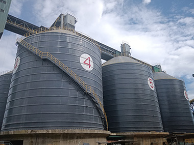
Steel silo plate rolling accuracy refers to the dimensional precision achieved when forming flat steel sheets into curved shell plates, typically measured by radius deviation, edge straightness, and thickness variation. High rolling accuracy matters because it directly determines shell plate fit-up quality during assembly, minimizes welding gaps, ensures uniform load distribution, and prevents structural weak points that could compromise the silo's long-term storage integrity.
Fundamentals of Plate Rolling in Steel Silo Construction
Figure 1Figure 2Figure 3
Why Plate Geometry Determines Silo Integrity
Every steel silo shell is assembled from individual curved plates whose rolled geometry must match the design radius within tight tolerances. A deviation of just ±2 mm on a 15-meter-diameter silo can accumulate to a 12 mm mismatch at the joint after 12 plates are installed. This cumulative error creates uneven stress concentrations, accelerates fatigue cracking at welded seams, and reduces the silo's rated storage capacity by up to 8% due to internal volume irregularities.
The Rolling Process Sequence
Plate rolling for steel silos follows a defined sequence: pre-bending of plate ends (typically 150–200 mm from each edge), progressive multi-pass rolling through the main curvature zone, and final calibration passes. Each pass advances the plate by 25–40 mm between roller engagements. For standard grain silo plates measuring 6–12 mm thickness and 1,500–2,500 mm width, the complete rolling cycle requires 8–15 passes depending on plate thickness and target curvature radius.
Material Behavior During Cold Rolling
Structural steel plates (Q235B, Q345B) exhibit elastic recovery (springback) of 2°–5° after the rolling load is removed. This springback must be compensated by over-rolling the plate beyond the target angle. The springback ratio increases linearly with yield strength and plate thickness—a 10 mm Q345B plate requires approximately 15% more over-rolling correction than an equivalent Q235B plate. Accounting for this behavior is the single most critical factor in achieving first-pass accuracy.
Key Parameters Controlling Rolling Accuracy
Roller Configuration and Pressure Settings
Four-roll plate bending machines provide superior accuracy over three-roll systems because the additional side roller eliminates the need for separate pre-bending. The upper roller diameter typically ranges from 300 mm to 600 mm depending on plate thickness capacity. Hydraulic pressure settings must be calibrated to within ±0.5 MPa; excessive pressure causes surface scoring and thickness reduction exceeding 0.3 mm, while insufficient pressure results in incomplete curvature transfer and radius overshoot of 3–5 mm.
Plate Thickness and Width Ratios
The thickness-to-width ratio (t/W) directly influences rolling behavior. Plates with t/W ratios below 0.004 (thin and wide) tend to develop edge waviness and require support rollers or guide systems. Plates with t/W ratios above 0.008 (thick and narrow) resist curvature formation and demand higher rolling forces. Optimal accuracy is achieved when the ratio falls between 0.004 and 0.007, which covers most silo shell plate specifications ranging from 6 × 1,800 mm to 12 × 2,500 mm.
Temperature Effects on Dimensional Stability
Rolling plates below 5°C increases yield strength by approximately 10–15%, significantly raising springback and the risk of surface cracking. Conversely, plates heated above 200°C during summer storage in direct sunlight exhibit reduced springback but increased thermal expansion distortion. The recommended ambient rolling temperature range is 15–35°C, with plate surface temperature verified by infrared thermometer before each rolling cycle.
Equipment and Technology for Precision Rolling
CNC Plate Rolling Machines
Modern CNC-controlled four-rolling machines achieve radius accuracy of ±1.5 mm on plates up to 40 mm thickness. The CNC system stores curvature programs for each silo diameter, automatically calculates pass sequences, and compensates for material springback using pre-calibrated algorithms. Servo-hydraulic systems maintain roller positioning accuracy of ±0.1 mm, and real-time feedback from encoders enables in-process correction without manual intervention.
Digital Radius Measurement Systems
Laser-based radius gauges mounted on the rolling machine provide continuous curvature measurement with 0.5 mm resolution. These systems compare the actual plate profile against the CAD-designed target curve and flag deviations exceeding ±2 mm. Integration with the CNC controller enables automatic pass adjustment, reducing rework rates from 12% (manual measurement) to under 3%.
Roller Surface Maintenance Protocols
Roller surface roughness must be maintained below Ra 3.2 µm to prevent plate surface damage. Worn or scored rollers imprint defects onto every plate, creating stress concentration points that reduce fatigue life by up to 20%. Scheduled roller regrinding every 500–800 operating hours, combined with daily surface inspection using dye penetrant testing, ensures consistent plate surface quality throughout production campaigns.
Quality Inspection and Tolerance Standards
Acceptable Tolerance Ranges
Industry-standard tolerances for steel silo shell plates specify: radius deviation ≤ ±3 mm, chord length variation ≤ ±2 mm, edge straightness ≤ 1.5 mm per meter, and diagonal difference ≤ 4 mm for standard plate sizes. These tolerances align with European Standard EN 1993-4-1 and Chinese Code GB 50322 for silo structures. Tighter tolerances (±1.5 mm radius) are required for silos storing abrasive materials where internal surface smoothness directly affects flow patterns and wear rates.
Inspection Methods and Frequency
Full-size template checking using steel radius gauges remains the primary verification method. Each plate is checked against a master template cut to the exact design radius with a 2 mm acceptance gap. For high-precision projects, 3D laser scanning generates a point cloud of the rolled plate that is overlaid on the CAD model, producing a color-coded deviation map with 0.3 mm resolution. Inspection frequency follows a 100% check for the first 5 plates (setup verification), then random sampling of 1 in 5 plates thereafter.
Documentation and Traceability
Each rolled plate receives a unique identification number linked to its rolling parameters (pass count, pressure settings, roller positions, ambient temperature) and inspection results. This digital traceability record enables root-cause analysis when field assembly reveals fit-up issues and supports warranty claims. Data is stored in the project quality management system for a minimum of 10 years, matching the typical silo design life documentation requirement.
Common Defects and Prevention Strategies
Edge Waviness and Buckling
Edge waviness occurs when thin plates (t < 8 mm) are rolled with excessive side roller pressure or insufficient main roller engagement. The waviness amplitude typically measures 3–8 mm over a 200 mm edge length. Prevention requires reducing side roller force by 20–30% for thin plates and increasing the number of calibration passes from 2 to 4. Post-rolling edge straightening using hydraulic presses can correct waviness up to 5 mm amplitude.
Radius Overshoot and Undershoot
Radius overshoot (plate too curved) results from insufficient springback compensation, while undershoot (plate too flat) indicates excessive over-rolling. Both conditions create assembly gaps exceeding the 3 mm maximum for submerged arc welding. Corrective re-rolling is possible for deviations up to 5 mm; beyond this threshold, the plate must be scrapped. Statistical process control charts tracking radius measurements across production batches help identify drift trends before defective plates are produced.
Surface Scoring and Thickness Reduction
Surface scoring from contaminated rollers or excessive localized pressure creates grooves 0.2–0.5 mm deep that act as fatigue crack initiation sites. Thickness reduction exceeding 5% of nominal plate thickness at any point violates structural design assumptions and requires plate rejection. Prevention includes daily roller cleaning, pressure limit enforcement through CNC interlocks, and ultrasonic thickness measurement at 500 mm grid intervals on each plate.
Pro Tip: Always roll a test plate from the first production batch and perform full dimensional inspection before proceeding with bulk production. This single step catches 90% of setup errors—incorrect roller spacing, wrong springback compensation values, or material batch variations—and prevents scrapping an entire production run. Document the test plate parameters as the baseline for all subsequent plates.
Case Study: 30,000-Ton Grain Silo Project
A large grain storage terminal required 28 steel silos, each 22 m diameter × 28 m height, constructed from 8 mm and 10 mm Q345B shell plates. The project specification demanded radius accuracy of ±2 mm and zero rework at field assembly. The rolling production line was equipped with a CNC four-roll machine (40 mm capacity), laser radius gauges, and automated pass sequencing. Over 1,840 plates were rolled across 6 production weeks. First-pass accuracy achieved 94% within ±2 mm tolerance, with the remaining 6% corrected through single re-roll passes. Field assembly recorded an average weld gap of 1.2 mm (specification limit: 3 mm), and zero plates were rejected at the construction site. The project was completed 11 days ahead of schedule, with the client reporting the tightest fit-up tolerances achieved across their portfolio of 15 silo terminals.
Frequently Asked Questions
What is the typical radius tolerance for steel silo shell plates?
Standard tolerance is ±3 mm for radius deviation, measured against a full-size template or 3D scan comparison. For high-precision applications such as cement or fly ash silos with abrasive contents, tighter tolerances of ±1.5 mm are specified to ensure smooth internal surfaces and uniform wear patterns.
How does plate thickness affect rolling accuracy?
Thicker plates (10–12 mm) require higher rolling forces and exhibit greater springback (3°–5°), demanding more precise over-rolling compensation. Thinner plates (6–8 mm) are prone to edge waviness and require reduced side roller pressure. The optimal thickness range for consistent accuracy without special measures is 8–10 mm.
Can rolled plates be corrected if they fall outside tolerance?
Yes, plates with radius deviations up to 5 mm can typically be corrected through 1–2 additional calibration passes. Deviations exceeding 5 mm, surface scoring deeper than 0.3 mm, or thickness reduction beyond 5% of nominal require plate scrapping. CNC-equipped machines reduce out-of-tolerance rates to under 3%, minimizing correction and scrap costs.
Partner with Manxing for Precision Silo Construction
Manxing delivers EPC silo contracting with in-house CNC plate rolling, achieving ±1.5 mm radius accuracy across projects worldwide. Our integrated manufacturing and construction approach eliminates fit-up issues, reduces field welding rework, and accelerates project schedules.