
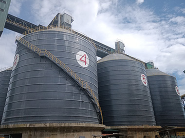

Steel Silo Stiffener Fabrication Tolerances: The Details That Keep Your Silo Standing
Stiffener fabrication tolerances are the allowable dimensional deviations in rolled, welded, and bolted ring stiffeners that keep a steel silo's shell from buckling under load. For most cement and clinder silos, that means controlling circumferential length to ±3mm, vertical straightness to 1:1000, and bolt-hole positional accuracy to ±1.5mm across the full ring circumference. Miss these, and you're not dealing with a "cosmetic issue" — you're looking at localized shell buckling, bolt-shear failures, or a ring that won't close on site. I've watched a 45m-diameter slag silo get delayed three weeks because one stiffener ring was 12mm oversized. The crane sat idle. The crew stood around. That's the cost of tolerance creep.
What Stiffener Tolerances Actually Control
Stiffeners on a steel silo aren't decorative. They're the ribs that keep the thin shell — usually 4mm to 12mm plate — from wrinkling under wind, seismic, and material load. The tolerance envelope controls five things simultaneously, and they all interact.
Circumferential Length Deviation
The total developed length of each stiffener segment has to match the theoretical circumference within a tight band. For bolted ring stiffeners on silos up to 30m diameter, we hold ±3mm on the total ring length. Go beyond that, and the splice gaps either won't close or you're forcing bolts into misaligned holes. I've seen crews use come-alongs to pull a ring closed — that's not assembly, that's damage.
For welded-on stiffeners (common on smaller coal and fly ash silos under 15m diameter), the tolerance tightens to ±2mm because you can't fudge a weld gap with a longer bolt. The EN 1993-4-1 standard gives you the framework, but shop-floor reality means you're checking every segment with a calibrated tape at 20°C, not at whatever temperature the plate happens to be sitting at in the yard.
Profile Straightness and Twist
A stiffener angle or channel that's twisted along its length creates a point load on the shell instead of a distributed one. We specify a maximum deviation of 1mm per 1000mm of stiffener length in any direction — vertical, horizontal, or twist. Check it with a straightedge and feeler gauge, not with your eye.
Here's where it gets annoying. A 6-meter length of L150×150×12 angle can easily pick up 4mm of twist during welding to the shell if you don't sequence the welds properly. We alternate sides, skip around, and keep interpass temperature under 250°C. Simple stuff. But I visited a fabrication shop in Jiangsu where they were welding one full side before touching the other. Every stiffener came out banana-shaped. They had to re-roll half the batch.
Bolt-Hole Positional Accuracy
For bolted ring stiffeners — the kind you see on large cement silos where the ring is split into 4 to 12 segments for transport — bolt-hole positional tolerance is ±1.5mm in any direction from the theoretical location. That's measured across the full ring after drilling, not per segment.
The trick is cumulative error. If each of your 8 segments has a +1mm drift in the same direction, you end up with 8mm total at the last splice. That's not a 1.5mm problem — that's a "drill new holes on site with a 3am torch" problem. We use a full-ring template for drilling, and we check every segment against the template before it leaves the shop. Template cost: maybe $800. Site rework: $15,000 and a week's delay.
How Tolerances Change by Stiffener Type
Not all stiffeners are created equal. The tolerance regime depends on the profile, the attachment method, and the structural role.
External Ring Stiffeners (Bolted)
These are the big ones — usually angle or channel sections running horizontally around the outside of the shell at intervals of 1.2m to 2.5m. They resist wind and vacuum loads. Because they're bolted in segments, the critical tolerances are:
- Segment arc length: ±3mm per segment
- Bolt-hole pitch: ±1.5mm (hole-to-hole within a splice plate)
- End-squareness of each segment: ±1mm across the flange width
The end-squareness one gets overlooked constantly. If the cut on the end of a stiffener segment isn't square to its own axis, the splice plate sits at an angle, the bolts go in cocked, and you're loading the bolt in bending instead of shear. A single M20 Grade 10.9 bolt in shear handles about 106kN. Put it in bending from a cocked splice, and you're down to maybe 40kN before things start moving. That's not a safety margin — that's a failure path.
Welded-on Stiffener Bands
Smaller silos — say under 18m diameter for fly ash or alumina — often use continuous stiffener bands welded directly to the shell. The tolerance focus shifts to:
- Shell-to-stiffener gap before welding: maximum 2mm (if it's more, you're not welding — you're filling)
- Weld leg size: typically 6mm to 8mm fillet, with a minimum of 5mm accepted after inspection
- Stiffener vertical position on shell: ±5mm from the theoretical elevation mark
The ±5mm vertical position tolerance sounds generous, but it matters when you're stacking shell courses. If a stiffener is 5mm too high, it interferes with the landing of the next shell course above it. I watched a crew in Vietnam spend two hours grinding a stiffener down because it was 7mm out of position. The shell plate above it wouldn't seat. Two hours of grinding versus 10 minutes of checking with a level during fit-up. Do the math.
Horizontal vs. Vertical Stiffener Orientation
Most silos use horizontal ring stiffeners because wind and vacuum loads are circumferential. But some tall, narrow silos — particularly those over 40m height-to-diameter ratio exceeding 3:1 — also need vertical stiffeners to prevent shell ovalization during discharge.
Vertical stiffeners have different tolerance priorities:
- Plumb (vertical straightness): 1:1000 maximum deviation over the full height
- Spacing between vertical stiffeners: ±10mm from theoretical position
- Base anchorage alignment: ±3mm from the anchor bolt pattern
That 1:1000 plumb tolerance means over a 30m height, you can have up to 30mm of lean. Sounds like a lot. But if two adjacent vertical stiffeners lean in opposite directions, the shell between them gets squeezed into an S-shape. That's local buckling waiting to happen under full material load.
Inspection Methods and Frequency
Tolerances are meaningless if you don't check them. Here's what we actually do on the shop floor, not what the quality manual says.
Dimensional Checks During Fabrication
Every stiffener segment gets three checks before it ships:
- Individual segment check: Length, straightness, hole position, end-squareness. Done on the bench with tape, straightedge, and a hole-position gauge.
- Full-ring assembly check (dry fit): All segments of a ring are assembled on a flat surface — usually the shop floor marked with a 1:1 ring outline — with all splice bolts installed to 50% torque. Total ring diameter, roundness, and splice gaps are recorded.
- Shell fit-up check: The first stiffener on each shell course is tack-welded or clamped in position and checked for gap, alignment, and elevation before full welding or bolting begins.
The dry-fit check is non-negotiable. I don't care how good your CNC drilling is — you assemble the ring on the ground before it goes on the silo. One project in Indonesia skipped this step to save two days. On site, the ring wouldn't close. They had to cut and re-weld splice plates at height, in tropical rain, with a crew of six. Took four days. The two days they "saved" cost them $22,000.
Tools and Equipment
You don't need a $50,000 CMM machine for stiffener inspection. You need:
- Calibrated steel tape (30m, ±1mm accuracy) for circumference checks
- Straightedge (2m, machined, with feeler gauges) for straightness
- Spirit level (0.5mm/m sensitivity) for plumb on vertical stiffeners
- Hole-position template or go/no-go gauge for bolt-hole alignment
- Ultrasonic thickness gauge if you're verifying stiffener material thickness (should match design ±0.5mm)
The one tool people forget? A temperature-calibrated tape. Steel expands at about 12×10⁻⁶ per °C. A 30m ring measured at 35°C versus 15°C reads about 7mm different. That's half your tolerance band, eaten by weather. We either correct for temperature or measure in the morning when the plate is at ambient. Simple. But I've seen QC reports where the "out-of-tolerance" finding was just a hot afternoon measurement.
Common Failure Modes from Tolerance Exceedance
What actually goes wrong when tolerances slip? Not theory — real outcomes.
Shell Buckling at Stiffener Locations
If a stiffener is locally twisted or has a kink, it creates a hard point on the thin shell. Under vacuum (common during pneumatic discharge), the shell wants to implode inward. The stiffener should resist that. But a kinked stiffener concentrates the load, and the shell buckles right at the stiffener — not between them, which is what the design assumes.
I inspected a 3,500-tonne cement silo in Egypt that had six buckles, all at stiffener locations. Every buckle was under a stiffener that had 3mm of twist over its length. The shell was 6mm plate. The buckles were 150mm deep. Repair cost: $45,000 and 10 days of scaffolding. The root cause? A fabricator who checked straightness visually instead of with a straightedge.
Bolt-Shear Failures at Splice Joints
When bolt holes are misaligned beyond the ±1.5mm tolerance, crews sometimes force bolts in or ream holes oversize. An M20 bolt in a 22mm hole (standard clearance) works fine. An M20 bolt in a 26mm hole (reamed out to fix misalignment) has 4mm of play. Under cyclic wind loading, that bolt works loose in 6 to 18 months.
The fix isn't bigger bolts — it's proper hole position. If you have to ream, the splice plate should be replaced, not the hole enlarged. EN 1090-2 is clear on this: holes may be reamed up to 2mm oversize maximum, and only with engineer approval. Beyond that, you're outside the standard and outside the structural model.
Progressive Ring Misalignment During Construction
Here's the cascade problem nobody talks about. Stiffener rings are installed as the shell is built upward. If Ring 3 is 4mm out of position, Ring 4 sits on shell that's already slightly off. By the time you reach Ring 12, you've accumulated 40mm of drift. The top of the silo is noticeably offset from the bottom.
This isn't just ugly — it affects roof connection, ladder alignment, and platform fit-up. We check cumulative ring position every three rings with a total station. If drift exceeds 15mm, we adjust the next shell course to bring it back. Catch it early, it's a 2mm shim. Catch it at the top, it's a structural modification.
Field Tip: The 3-Ring Rule
Check cumulative stiffener ring position with a total station every three rings during construction. Maximum allowable cumulative drift: 15mm from the theoretical axis. If you exceed it, correct on the next shell course — don't wait until the top. A 2mm shim plate under a shell course is a $50 fix. A roof-to-shell connection that doesn't fit at 45m height is a $5,000+ rework.
Case Study: 28m Diameter Clinker Silo — Stiffener Tolerance Recovery
Project: 8,000-tonne clinker silo, 28m diameter × 38m height, 12 stiffener rings, external bolted angle stiffeners L200×200×16.
Problem discovered: During shop inspection, 6 of 12 stiffener rings showed circumferential length deviations of +5mm to +8mm beyond the ±3mm tolerance. The fabricator had been cutting segments based on a template that was itself 6mm oversized — a transcription error from the shop drawing.
What we did:
- Rejected all 6 non-conforming rings (72 segments total)
- Fabricator rebuilt using a corrected template verified against the structural drawing
- New rings were dry-assembled on the shop floor and checked: all within ±2mm, better than the ±3mm spec
- Inspection frequency increased from 1 in 5 segments to 100% for the replacement batch
Cost: $18,000 in rework and 5-day schedule impact. The alternative — accepting the out-of-tolerance rings — would have meant forced bolt-ups on site, potential shell distortion, and a likely call-back within 2 years. The client initially pushed back on the rejection. We showed them photos of the Egyptian silo buckles. They approved the rework the same day.
FAQ
Q: What happens if a stiffener ring is slightly oversized — say 5mm over on a 25m diameter silo?
On a 25m diameter ring (approximately 78,540mm circumference), 5mm oversize means the splice won't close without forcing it. You can sometimes pull it with a chain come-along, but you're pre-loading the bolts and distorting the shell locally. The correct fix is to remove one segment, trim it to length, and re-drill the splice holes. Don't ream existing holes larger to make it fit — that compromises the splice capacity and violates EN 1090-2.
Q: Are tolerance requirements different for seismic zones?
Yes, and tighter. In seismic design categories D, E, and F (per EN 1998-4 or ASCE 7), stiffener tolerances should be reduced by about 30%. That means ±2mm instead of ±3mm on circumferential length, and ±1mm instead of ±1.5mm on bolt-hole position. The reason: seismic loads are cyclic and reversal. A stiffener that's slightly out of tolerance won't cause immediate failure under static load, but under 20+ cycles of seismic loading, the stress concentration at a kinked or misaligned stiffener accelerates fatigue cracking. We learned this the hard way on a project in Chile — post-earthquake inspection found cracks at three stiffener splices that had been assembled with 3mm hole misalignment.
Q: Can I use laser scanning instead of manual measurement for stiffener inspection?
You can, and for large rings it's faster. A terrestrial laser scanner picks up 100,000+ points per second and gives you a full 3D model of the assembled ring. Deviation from CAD is color-mapped instantly. But — and this is important — laser scanning accuracy is typically ±2mm at 10m range. That's right at the edge of your tolerance band. We use laser scanning for gross geometry verification (is the ring round? is it the right diameter?) and manual measurement for the critical splice and hole-position checks. Also, scanning doesn't replace the dry-fit bolt-up test. A ring can scan perfectly and still have a bolt that won't go in because of burr or paint thickness. Old school wins for final acceptance.
Get Your Stiffener Tolerances Right the First Time
At Manxing, we fabricate, inspect, and deliver stiffener systems for silos up to 60m diameter across 30+ countries. Every ring is dry-fit assembled before shipment. Every bolt-hole pattern is verified against a full-ring template. Every inspection report includes actual measurements — not just "pass/fail."
If you're specifying a new silo or troubleshooting fabrication issues on an existing project, our engineering team can review your tolerance specifications, audit your fabricator's QC process, or supply pre-verified stiffener assemblies direct from our facility.
Contact our silo engineering team: manxingstorage.com — send us your silo diameter, height, and material type, and we'll respond within 24 hours with a stiffener specification sheet including all applicable tolerances and inspection hold points.