

Seismic Design Considerations for Industrial Steel Silos: What Every EPC Project Must Address
Seismic design for steel silos isn't optional — it's the difference between a structure that survives a 0.3g event and one that buckles at the hopper seam. The two things that matter most: your anchorage system and the wall-to-hopper junction. Get those wrong and the rest of your engineering doesn't matter. Here's what we've learned from designing silos in seismic zones across 30+ countries.
Why Silos Fail Differently Than Buildings in Earthquakes
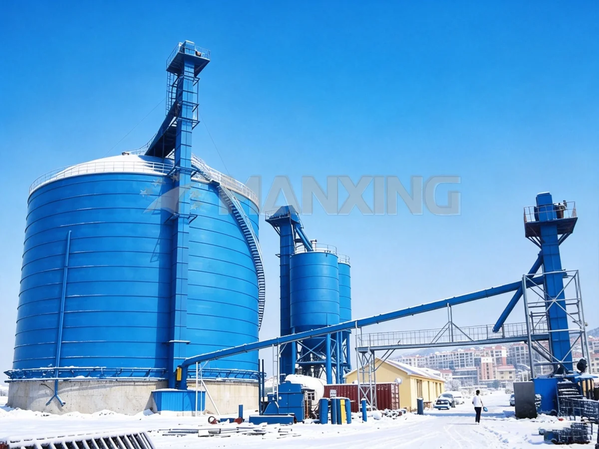
Buildings are designed for ductility. You expect a steel frame to yield, absorb energy, and maybe need repair after a big one. Silos don't work that way. A cement silo holding 5,000 tonnes of clinker is a concentrated mass sitting on a relatively narrow footprint. The dynamic behavior is completely different from a multi-story building, and the failure modes are nastier.
The Hopper-Bottom Problem Nobody Talks About
The junction between the cylindrical wall and the conical hopper is the single most vulnerable point in a steel silo under seismic load. During lateral shaking, the mass of the stored material pushes outward against the wall, but the hopper geometry creates a discontinuity in stiffness. Stress concentrates right at that weld seam. I've seen circumferential buckling at the wall-to-hopper junction on silos that were otherwise perfectly designed. The buckling wave was maybe 400mm tall, running around the entire circumference. The silo didn't collapse, but it was out of service for four months.
Eurocode 8 (EN 1998-4) addresses this with specific provisions for shell structures, but the code assumes you've got a clean, uniform geometry. Real silos have manholes, reinforcement pads, ladder attachments, and nozzle penetrations that all disrupt the stress path. You can't just apply the code blindly.
Mass Distribution and the Sloshing Effect
Here's something that catches people off guard: the stored material doesn't move as a rigid block. During seismic excitation, the upper surface of the bulk solid shifts — not like liquid sloshing, but as a shear deformation through the mass. For a 12m-diameter cement silo, the effective mass participating in the first lateral mode might be only 60-70% of the total inventory. The rest is "locked" in the lower sections by internal friction.
But that remaining 30-40%? It's moving, and it's generating overturning moments that your foundation has to resist. We ran a time-history analysis on a 3,000-tonne fly ash silo in Indonesia and found the overturning moment at the base was 22% higher than what a simple equivalent static method predicted. The difference came entirely from the phase relationship between the silo wall deformation and the internal material movement.
Soil-Structure Interaction That Changes Everything
Most seismic analyses assume a fixed base. That's fine for a silo sitting on rock. But put that same silo on 8m of soft alluvial clay — which is exactly what we had on a project in Bangladesh — and the foundation period lengthens enough to shift the system into a completely different part of the response spectrum. The spectral acceleration at the shifted period was nearly double what the fixed-base analysis gave us.
We ended up having to redesign the foundation from a simple ring beam to a piled raft with 24 bored piles, each 14m deep. The client wasn't happy about the cost increase, but the alternative was a silo that would have resonated with the site soil during a design-level event. Not a conversation you want to have after the fact.
The Standards That Actually Govern Silo Seismic Design
You'd think there'd be one clear standard for this. There isn't. You're juggling structural codes, silo-specific provisions, and local building requirements that sometimes contradict each other.
Eurocode 8 and EN 1991-4: The European Framework
EN 1991-4 (Eurocode 1, Part 4) gives you the load patterns for silos — how the stored material presses against the wall during filling and discharge. EN 1998-4 (Eurocode 8, Part 4) adds the seismic provisions specific to tanks and silos. Together they form the most complete framework available for silo seismic design.
But here's the catch: EN 1998-4 was written primarily for liquid storage tanks. The provisions for solid-material silos are thinner, and some of the assumptions don't translate cleanly. The code's approach to internal pressure from stored solids during seismic events is, frankly, underdeveloped. We supplement it with FEA modeling and project-specific judgment.
GB 50011 and Chinese Seismic Codes
For projects in China, GB 50011 (Code for Seismic Design of Buildings) is the governing document. It classifies sites into four seismic design categories based on ground acceleration — from 0.05g up to 0.40g for the highest intensity zones. The code requires that silos in intensity 8 zones (0.20g design basis) undergo time-history analysis if the structure exceeds 24m in height or stores materials with explosive potential.
We've designed silos in Yunnan province under GB 50011 requirements. The local enforcement is strict — the review institute checked every load combination, every buckling mode, every anchor bolt calculation. Took three rounds of submission before they signed off. But the process caught a mistake in our wind-seismic combination factor that we'd have missed otherwise. I'll take bureaucratic rigor over a silent error any day.
When Standards Conflict — What We Actually Do
On a project in Turkey, we had a client specifying ACI 318 for the foundation (American standard) while the silo shell itself was designed to EN 1993-4-1 (European shell design). The seismic input came from the Turkish Seismic Code, which maps roughly to Eurocode 8 but with different importance factors. Three codes, three sets of safety factors, three different philosophies on load combinations.
We built a unified model in SAP2000 and ran the analysis under all three code frameworks simultaneously. The governing case — the one that drove the final design — came from the Turkish code's requirement for an accidental eccentricity of 5% of the silo diameter. That eccentricity added a torsional component that neither Eurocode nor ACI explicitly required for this geometry. The shell thickness went from 8mm to 10mm at the lower rings. Not a huge change, but it's the kind of thing that keeps you up at night if you miss it.
Structural Failure Modes We've Seen in the Field
Paper analysis is one thing. Standing in front of a damaged silo after an earthquake is another. Here's what actually happens.
Circumferential Buckling at the Wall-to-Hopper Junction
This is the big one. The conical hopper acts as a stiff ring at the base of the cylindrical shell, but the transition isn't smooth. Under lateral seismic load, the shell tries to ovalize — the cross-section deforms from circular to elliptical. The hopper resists this deformation, creating a hard point. The shell buckles just above this hard point, usually in a diamond-pattern or elephant-foot buckling mode.
After the 2010 Chile earthquake (magnitude 8.8), we inspected a cluster of six cement silos at a port facility. Two of them had buckled at the wall-to-hopper junction. The buckles were 300-500mm deep, running 60-90 degrees around the circumference. Both silos were anchored with 24 M30 bolts on a 10m-diameter ring — which should have been adequate. The problem was the anchor bolts were embedded in a foundation ring beam that was only 400mm deep. The beam itself rotated under overturning moment, effectively loosening the bolts on the tension side. The silo didn't fall over, but the shell was permanently deformed.
Anchor Bolt Failure Patterns
Anchor bolts fail in three ways under seismic load: pull-out from the concrete, yielding and fracture at the thread root, or — most commonly — a combined mode where the concrete cone develops first, then the bolt stretches and the nut walks off the thread. We specify minimum embedment of 16 times the bolt diameter for seismic zones, with a concrete cone spacing that prevents overlapping failure surfaces.
For a 6,000-tonne clinker silo in a Zone 4 seismic area, we used 36 M36 anchor bolts, each embedded 600mm into a 900mm-deep ring foundation. The bolts were Grade 8.8 with a proof load of 830 MPa. The design pull-out force per bolt under the seismic load combination was 285 kN — well within the bolt's capacity, but the concrete cone capacity governed. We had to increase the foundation ring width from 800mm to 1,100mm just to get the cone geometry right.
Lateral Support and Stiffener Collapse
Tall silos — anything over 25m — often need external stiffeners to resist wind and seismic ovalization. These stiffeners are typically rolled steel sections welded to the shell. Under cyclic seismic loading, the stiffener-to-shell weld is a fatigue crack waiting to happen. We specify full-penetration welds for stiffener attachments in seismic zones, with ground smooth transitions at the toe. No exceptions.
I remember a project in Malaysia where the contractor substituted a fillet weld for the specified full-penetration joint on the stiffener connections. We caught it during a site visit — the weld was maybe 6mm fillet on a 12mm stiffener plate. That's a fatigue detail that would have cracked within a few seismic cycles. We cut them all out and re-welded. The contractor argued it was "strong enough." It wasn't.
Design Strategies That Actually Work
After enough projects, you develop a set of rules that go beyond the code minimums. Here's what we've found makes a real difference.
Stiffener Placement and Spacing
For silos in seismic zones, we place horizontal stiffeners at intervals no greater than 1.5 times the shell diameter. The stiffener itself needs a minimum moment of inertia of 1.2 × 10⁶ mm⁴ per millimeter of shell width — that's the threshold where it actually contributes to shell stiffness rather than just adding mass. Below that, you're welding steel to the wall for no structural benefit.
We also add a compression ring at the top of the silo — a rolled angle or channel that prevents the shell edge from buckling under the combined effect of roof loads and seismic overturning. It's a simple detail, maybe 200kg of steel on a large silo, but it stops the top course from folding inward during a lateral event.
Foundation Isolation — When It Makes Sense
Base isolation for silos is rare but not unheard of. We evaluated it for a 4,000-tonne alumina silo in a Japanese facility where the client wanted to protect both the structure and the material from seismic damage. The isolation system used 12 lead-rubber bearings, each with a design displacement of ±250mm.
The analysis showed the isolated period would be 2.8 seconds — well-separated from the site's predominant period of 0.6 seconds. The spectral acceleration dropped by a factor of 3.5 compared to a fixed-base design. The catch: the bearing cost was $180,000, and the moat around the foundation had to accommodate 300mm of displacement in any direction. The client went with it. For a facility where downtime costs $50,000 per hour, the payback was obvious.
Wall Thickness Transitions
We don't use a constant wall thickness. The lower courses of a silo carry the cumulative weight of everything above them, plus the seismic shear that accumulates toward the base. Our typical approach: the bottom course is 2-3mm thicker than the top course, with intermediate steps every 3-4 courses. For a 15m-tall silo, that might mean 6mm at the top, 8mm in the middle, and 10mm at the bottom.
The transition has to be on the outside face — the inside must remain flush so material flow isn't disrupted. We use external butt welds with full penetration, ground smooth on the inside. It adds fabrication cost, but it eliminates the step-change in stiffness that would otherwise create a stress concentration at the course boundary.
Case Study: 5,000-Tonne Cement Silo in Seismic Zone 4, Philippines
A cement plant in Luzon needed a 5,000-tonne cement silo on a site classified as Seismic Design Category D under the local code (which maps to IBC/ASCE 7). The site had a design spectral acceleration of 0.55g at short periods. The silo was 32m tall, 14m in diameter, with a 60-degree conical hopper and a nominal wall thickness of 8mm.
Our initial equivalent static analysis gave a base shear of 1,850 kN and an overturning moment of 28,400 kN·m. But when we ran the time-history analysis with seven spectrum-compatible accelerograms, the results were different: base shear peaked at 2,340 kN (26% higher) and the overturning moment hit 34,100 kN·m. The difference came from higher-mode contributions — the second and third modes of the shell were adding localized stress concentrations that the static method completely missed.
We redesigned the wall-to-hopper junction with a reinforced transition ring — a 200mm × 200mm × 12mm angle welded continuously to the shell, with gusset plates every 600mm. The anchor system went to 40 M39 bolts on a 1,200mm-wide ring foundation, embedded 700mm into C35/45 concrete. The foundation itself was a 1.5m-thick raft on 18 bored piles, each 16m deep, socketed into weathered rock.
The silo was commissioned in 2019. In 2023, a magnitude 6.2 earthquake hit the region — peak ground acceleration at the site was estimated at 0.38g. Post-event inspection showed no visible deformation, no bolt loosening, no cracks in the shell or foundation. The plant was back in operation within 48 hours. That's what good seismic design looks like in practice.
FAQ
Q: Can I use the same silo design in a seismic zone as in a non-seismic zone?
No. The wall thickness, anchor system, and foundation all change. In our experience, moving from a non-seismic to a Zone 3 seismic design typically increases the steel weight by 15-25% and the foundation concrete volume by 30-40%. The anchor bolt count often doubles. Trying to use a non-seismic design in a seismic zone is a false economy — you'll either fail the local building review or fail in the first earthquake.
Q: What's the minimum seismic analysis required for a steel silo?
It depends on the code jurisdiction and the silo geometry. Under Eurocode 8, silos under 25m in height in low-seismic zones can use the equivalent static method. Above that, or in higher seismic zones, you need a modal response spectrum analysis. For critical facilities or unusual geometries, time-history analysis is the right call. Under GB 50011, silos over 24m in intensity 7 or 8 zones require time-history analysis regardless. When in doubt, run the more detailed analysis. The cost of the analysis is trivial compared to the cost of being wrong.
Q: How often should anchor bolts be inspected after an earthquake?
Immediately. Within 24 hours if possible. Check for visible loosening, nut rotation, or concrete cracking around the bolt heads. If the event exceeded 50% of the design basis acceleration, do a full torque check on every bolt. If it exceeded 75%, add ultrasonic bolt tension measurement to verify preload. We've seen bolts that looked fine visually but had lost 60% of their preload due to concrete micro-cracking. You can't see that with your eyes.
Need a Silo Design That Survives the Next Earthquake?
Manxing has designed and built steel silos in seismic zones across 30+ countries — from the Philippines to Chile, Turkey to Indonesia. We don't just run the analysis; we've stood in front of damaged silos and know what failure looks like before it happens. Our EPC team handles everything from geotechnical assessment through commissioning, with full compliance to Eurocode, GB, AISC, and local seismic requirements.
Contact our engineering team for a project-specific seismic assessment: manxingstorage.com