
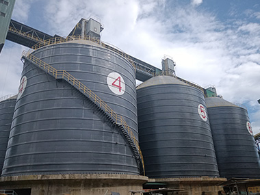

Wind Load Analysis and Structural Sizing of Large-Diameter Silos: What Every EPC Contractor Needs to Get Right
Wind load governs the structural design of large-diameter silos more often than any other single load case — and getting it wrong costs you the shell, the foundation, or both. The applicable standards are EN 1991-1-4 for wind actions and EN 1993-4-1 for shell structures, with ASCE 7-22 as the North American equivalent. This article walks through the calculation framework, the sizing methodology, and the field mistakes that don't show up in textbook examples.
1. Why Wind Load Dominates Silo Structural Design
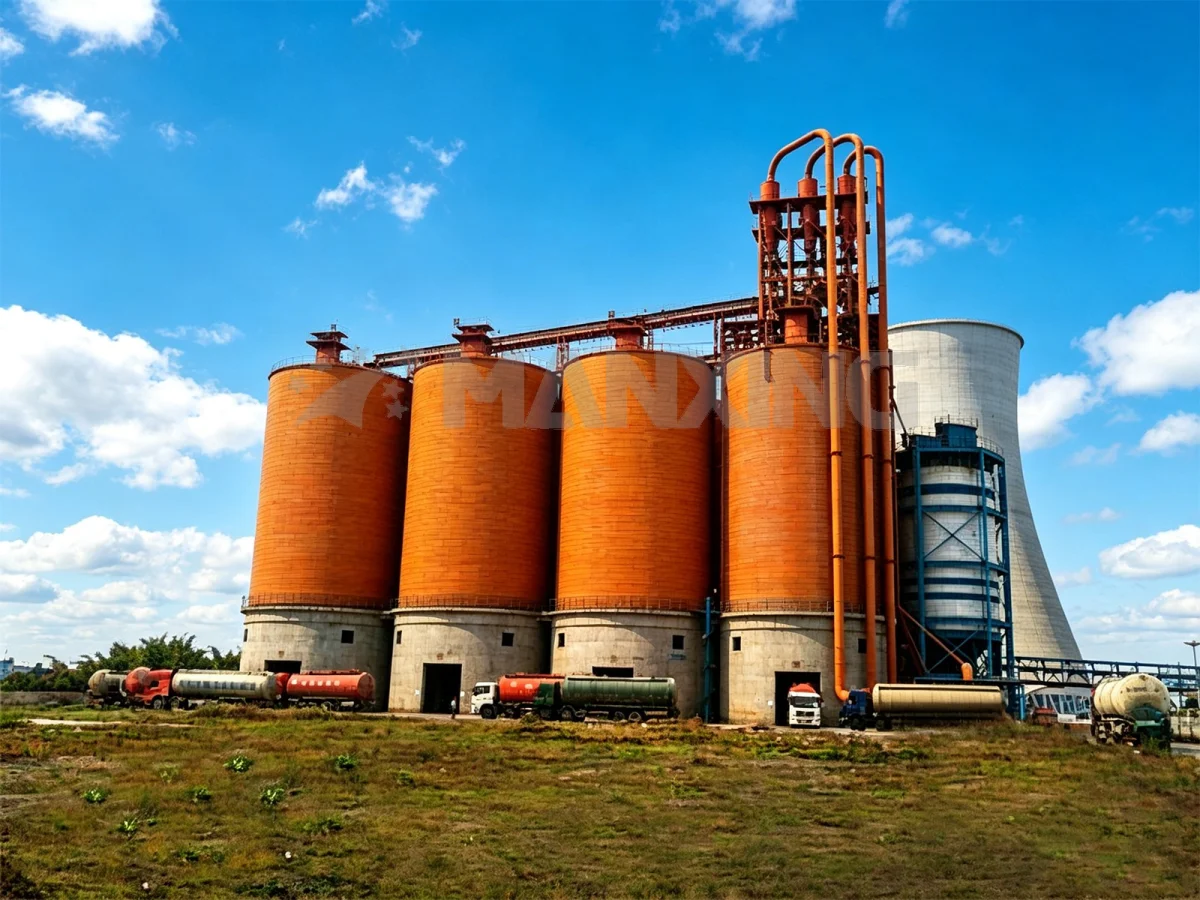
The Physics of Wind on Cylindrical Structures
A silo is essentially a vertical cylinder sitting in open terrain. That shape is aerodynamically nasty. Wind doesn't just push against the windward side — it wraps around, creates suction on the leeward and side surfaces, and generates vortices that oscillate the shell. The net effect is a pressure distribution that's nothing like the uniform load most structural engineers are used to dealing with.
For a 30-metre-diameter silo standing 40 metres tall in open country, the total wind force can exceed 800 kN. That's not a typo. And that force isn't static — it fluctuates, it shifts direction, and it creates a massive overturning moment at the base. I've seen projects where the wind load case produced a base moment 2.3 times larger than the full-material gravity load case. The silo was designed for the material. It should have been designed for the wind.
When Wind Becomes the Governing Load Case
Here's the thing. For tall, slender silos — height-to-diameter ratios above about 1.5 — wind almost always governs. For short, squat silos storing dense material like clinker or limestone, gravity loads might control the shell thickness. But the anchorage, the foundation, and the base ring? Those are wind-driven in nearly every case.
The empty silo condition is usually the critical one. No internal material pressure, no frictional restraint on the shell, just a thin-walled cylinder trying to resist a lateral force that's trying to peel it off the foundation. I remember a project in Vietnam — a 25-metre-diameter cement silo, 38 metres tall. The client wanted to skip the empty-case wind analysis because "it's only empty during maintenance." We ran the numbers anyway. The anchor bolts they'd specified were undersized by 40%. They would have pulled out in a typhoon. We caught it in the drawing stage. That's a four-hour calculation that saved a six-month rebuild.
2. Wind Load Calculation Framework
Determining Design Wind Speed and Exposure
Start with the basic wind speed. EN 1991-1-4 uses a 10-minute mean wind speed at 10 metres above ground, with a 50-year return period. For most of Southeast Asia, that's in the range of 28–35 m/s. For typhoon-prone coastal areas — Philippines, southern China, Vietnam — you're looking at 45–65 m/s. ASCE 7-22 uses a 3-second gust speed, which is higher numerically but represents a different averaging period. Don't mix them up. I've seen a design team use a 3-second gust value in a Eurocode calculation and over-design the structure by 30%. Expensive mistake, but at least it was conservative.
Exposure category matters more than people think. EN 1991-1-4 defines four terrain categories. Most industrial sites fall into Category II — agricultural land with scattered obstacles. But a silo on a coastal plain with no trees for 2 kilometres? That's Category I, and the wind speed at height increases faster. A 40-metre-tall silo in Category I terrain sees roughly 15% more wind pressure at the top than the same silo in Category II. That difference changes your stiffener spacing.
Pressure Coefficients for Silo Shells
The external pressure coefficient (Cpe) for a cylindrical shell isn't a single number. It varies around the circumference. EN 1993-4-1 gives you a distribution: Cpe = -0.65 on the windward side near the stagnation point, dropping to about -1.0 on the sides, and reaching -0.4 to -0.5 on the leeward side. The negative sign means suction — the wind is pulling the shell outward on the sides, not just pushing it inward on the front.
For the top of the silo, you need to account for the roof structure. A conical roof with a 15° pitch has a Cpe of about -0.8 to -1.2 depending on the height-to-diameter ratio. A flat roof is worse — suction coefficients can hit -1.5. That uplift on the roof adds directly to the overturning moment. For a 30-metre-diameter flat-roof silo, the roof uplift alone can contribute 15–20% of the total base overturning moment.
Internal Pressure and Suction Effects
Don't forget the internal pressure coefficient (Cpi). A silo with openings — vents, manholes, conveyor inlets — has a positive internal pressure that adds to the external suction. EN 1993-4-1 allows you to calculate Cpi based on the opening area. If openings exceed 5% of the shell surface area, you're required to assume the silo is "permeable" and apply a Cpi of +0.2 or -0.3 depending on the wind direction relative to the openings.
In practice, most large silos have enough openings that you're dealing with the worst-case combination: maximum external suction plus maximum internal pressure. That combination can produce a net inward pressure on the shell of 1.5–2.5 kPa. For a thin shell — say, 6 mm wall thickness on a 30-metre-diameter silo — that's the difference between stable and buckled.
3. Structural Sizing: Shell, Stiffeners, and Hopper
Shell Thickness and Buckling Under External Pressure
The shell doesn't fail from wind pressure directly. It fails from buckling. A thin cylindrical shell under uniform external pressure buckles at a critical pressure that depends on the diameter-to-thickness ratio and the boundary conditions. The classical formula gives you a critical buckling pressure of roughly:
pcr = 0.92 × E × (t/D)^(2.5) / (L/D)
where E is the elastic modulus, t is thickness, D is diameter, and L is the unsupported length. For a 30-metre-diameter silo with a 6 mm shell and 8 metres of unsupported height, that works out to about 0.8 kPa. If your wind suction is 1.5 kPa, you've got a problem.
The fix is ring stiffeners. They break the unsupported length into shorter segments, which dramatically increases the buckling resistance. Each ring stiffener effectively creates a new boundary condition. With stiffeners spaced every 2 metres instead of every 8 metres, the buckling resistance goes up by a factor of roughly 16. That's not a linear relationship — it's the power of shell stability theory.
Ring Stiffener Design
Ring stiffeners on silos are typically welded steel angles or channels attached to the shell exterior. The required cross-sectional area depends on the wind load, the shell diameter, and the stiffener spacing. EN 1993-4-1 gives you a formula for the required section modulus:
As = (peff × D²) / (2 × fy × γm)
where peff is the effective wind pressure, D is the diameter, fy is the yield strength, and γm is the material safety factor. For a 30-metre silo with 1.5 kPa wind pressure and S355 steel, you're looking at a required area of about 1,200 mm² per metre of circumference. An L150×150×15 angle gives you 4,300 mm² — plenty, with margin for corrosion.
But here's where it gets tricky. The stiffener doesn't act alone. The shell contributes a "effective width" to the stiffener section — typically 1.56√(Rt) on each side, where R is the radius and t is the shell thickness. For a 15-metre radius and 6 mm shell, that's about 240 mm of effective shell width on each side. That's a lot of free stiffness. Ignore it and you're over-designing. Count on it without checking the weld detail and you're under-designing.
Hoppers and the Transition Zone
The hopper is where the shell meets the foundation, and it's where the wind load path gets complicated. The overturning moment from wind has to be transferred through the shell into the hopper, then into the base ring, then into the foundation. Every connection in that chain has to be checked.
The transition zone — the last metre or two of shell above the hopper — sees the highest combined stresses. Wind-induced bending, material pressure, thermal effects, and the stiffness discontinuity at the hopper junction all converge there. I've seen cracks develop in this zone on silos that were otherwise adequately designed. The fix is usually a thicker shell section — 8 mm instead of 6 mm — over the bottom 2 metres, plus a continuous fillet weld at the hopper-to-shell junction instead of an intermittent one.
4. Dynamic Wind Effects Most Engineers Underestimate
Vortex Shedding and Across-Wind Response
Steady-state wind pressure is only half the story. When wind flows past a cylindrical shell, it sheds vortices alternately from each side. This creates an oscillating pressure pattern — across-wind excitation — that can cause resonance if the vortex shedding frequency matches the natural frequency of the silo.
The vortex shedding frequency is given by the Strouhal relation: fs = St × V / D, where St is the Strouhal number (about 0.2 for a smooth cylinder), V is the wind speed, and D is the diameter. For a 30-metre silo in a 20 m/s wind, that's a shedding frequency of about 0.13 Hz. If the silo's first natural frequency is close to that — and for a thin-shell steel silo, it often is — you get lock-in. The vortices synchronize with the shell motion, and the oscillations amplify.
EN 1991-1-4 Clause 7.9 gives you the procedure for checking vortex shedding on cylindrical structures. The critical wind speed for resonance is Vcrit = fn × D / St. If Vcrit falls within the range of expected wind speeds at the site, you need to either add damping, modify the shell stiffness, or install helical strakes. I've used strakes on three projects — all coastal sites with sustained high winds. They work, but they add about 2% to the shell steel weight and they're a maintenance headache. Most clients prefer to stiffen the shell instead.
Wind-Induced Ovaling
There's another dynamic effect that doesn't get enough attention: ovaling. The non-uniform wind pressure around the circumference causes the circular shell to deform into an oval shape. This is a static effect, but it interacts with the dynamic vortex shedding in ways that can accelerate fatigue at welded joints.
The ovaling amplitude depends on the shell stiffness and the pressure distribution. For a 30-metre silo with 6 mm shell and ring stiffeners at 2-metre spacing, the peak-to-peak ovaling under design wind is typically 15–25 mm. That sounds small, but it's enough to cause fatigue cracking at the top of the hopper-to-shell weld after 10–15 years of cyclic loading. The solution is a thicker shell at the transition zone and full-penetration welds instead of fillet welds. It costs about 8% more in fabrication. It eliminates a failure mode that shows up in year 12.
5. Foundation and Anchorage Under Uplift
Overturning Moment and Base Plate Design
The wind overturning moment at the base of a large silo is enormous. For a 30-metre-diameter, 40-metre-tall cement silo in a 40 m/s wind zone, the overturning moment can reach 12,000–15,000 kN·m. That moment has to be resisted by the weight of the silo plus its contents, transferred through the base plate into the foundation.
The base plate is usually a thick steel ring — 30 to 50 mm — welded to the bottom of the shell and anchored to the concrete foundation with high-strength bolts. The plate thickness is governed by the bending stress from the overturning moment. For a 30-metre silo with a 2-metre-wide base plate, a 15,000 kN·m moment produces a maximum bending stress of about 180 MPa in a 40 mm plate. That's within the yield strength of S355 steel, but you need to check the fatigue life too. Cyclic wind loading means the base plate sees stress reversal. EN 1993-4-1 requires a fatigue assessment for silos in wind zones above 30 m/s.
Anchor Bolt Sizing
Anchor bolts are the last link in the chain, and the one most likely to be under-designed. The uplift force from the overturning moment is concentrated on the windward side of the base ring. For a 30-metre silo with a 15,000 kN·m overturning moment, the maximum uplift on a single anchor bolt group can exceed 200 kN.
M36 class 8.8 bolts have a design tension capacity of about 180 kN in concrete with a 300 mm embedment depth. You need at least two bolts per anchor point on the windward quarter of the silo, spaced no more than 500 mm apart. For high-wind zones, I specify M42 or M48 bolts with 400–500 mm embedment. The concrete foundation needs to be checked for cone failure too — the breakout capacity of a single bolt in C30/37 concrete with 400 mm embedment is about 220 kN. That's your limiting factor more often than the bolt itself.
6. Case Study: 30m Cement Silo in a Typhoon Zone
A recent project — a 30-metre-diameter, 42-metre-tall cement silo for a grinding station in the Philippines. Design wind speed: 55 m/s (3-second gust), which converts to about 38 m/s 10-minute mean for Eurocode calculations. Site exposure: Category I, coastal plain with no significant obstacles within 5 kilometres.
The silo stores 8,000 tonnes of cement. Shell material: Q345B (equivalent to S355). Shell thickness: 8 mm upper section, 10 mm lower section, 12 mm transition zone. Ring stiffeners: L160×160×12 at 1.8-metre spacing on the upper shell, L200×200×16 at 1.5-metre spacing on the lower shell. Hopper: 16 mm thick, conical, 30° pitch.
Wind load analysis per EN 1991-1-4 and EN 1993-4-1 gave a peak external suction of 1.8 kPa on the shell sides. The empty-silo wind case produced a base overturning moment of 14,200 kN·m. The full-material case produced only 9,800 kN·m. Wind governed by 45%.
Base plate: 45 mm thick, 2,200 mm wide, S355 steel. Anchor bolts: M48 class 8.8, 450 mm embedment, 24 bolts total on the windward half, 12 on the leeward half. Foundation: 1.2-metre-thick reinforced concrete mat, C40/50 concrete, 30-metre diameter.
Vortex shedding check: first natural frequency of the empty silo was 0.18 Hz. Critical wind speed for resonance: 32 m/s. That's within the range of expected typhoon wind speeds, so we added helical strakes to the upper 15 metres of the shell. The strakes added 1.8 tonnes of steel and about $4,200 to the fabrication cost. The client accepted it after we showed them the fatigue life calculation without strakes: 7 years to crack initiation at the top ring stiffener weld. With strakes: 25+ years.
Commissioning was in March 2023. Typhoon Malakas hit the site in November 2023 with sustained winds of 42 m/s. The silo performed without incident. The strakes did their job.
Frequently Asked Questions
Q: Can I use ASCE 7 wind loads with Eurocode silo design?
A: Not directly. ASCE 7-22 gives you a 3-second gust speed. EN 1991-1-4 uses a 10-minute mean speed. The conversion factor is roughly 0.65–0.70 depending on the terrain and averaging time. You also need to convert the pressure coefficients — ASCE 7 uses a different sign convention and different shape factors for cylindrical structures. The safest approach is to pick one code system and stick with it throughout the analysis. Mixing codes is how you get a silo that's 20% over-designed in one direction and 15% under-designed in another.
Q: How many ring stiffeners do I need on a 25-metre-diameter silo?
A: It depends on the wind zone and the shell thickness, but as a starting point: for a 25-metre silo with 6 mm shell in a moderate wind zone (30 m/s), you need stiffeners at roughly 2-metre spacing. That's about 12–14 rings for a 25-metre-tall shell. In a high-wind zone (45 m/s), reduce the spacing to 1.5 metres and increase the stiffener section by one size. Always run the buckling check per EN 1993-4-1 — the spacing isn't a rule of thumb, it's a calculated result.
Q: What's the most common wind-related failure mode in large silos?
A: Anchor bolt pullout. Not shell buckling, not base plate bending — anchor bolts. The reason is simple: the bolts are the one component that's designed by the foundation engineer, not the silo engineer, and the load path from shell to foundation is often poorly coordinated. I've seen projects where the silo designer specified M36 bolts and the foundation designer used M24 because "the concrete can take it." The concrete couldn't. The bolts pulled out in the first storm. Specify your anchor bolts on the silo drawings and make them part of the silo supply contract. Don't leave it to the foundation contractor to interpret.
Get Your Wind Load Analysis Right the First Time
Manxing has designed and commissioned large-diameter silos in 30+ countries, including typhoon zones, coastal exposures, and high-altitude sites with extreme wind conditions. Our engineering team runs full EN 1991-1-4 and EN 1993-4-1 wind analyses on every project — not just the gravity load cases. We've caught anchor bolt undersizing, missing stiffener rings, and vortex shedding resonance in the drawing stage, before steel was cut.
If you're planning a new silo project in a high-wind area, send us your site coordinates and material specs. We'll run a preliminary wind load assessment and tell you what the structure actually needs — not what the spreadsheet guesses.