
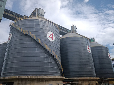

Silo Wall Thickness Calculation: Engineering Method
Silo wall thickness isn't a guess. It's governed by lateral pressure from the bulk material and buckling resistance under axial loads. We calculate it using EN 1993-4-1 or ASME standards, applying safety factors to the worst-case filling and discharge scenarios. Get it wrong, and the wall buckles. Get it right, and the silo stands for 30 years.
The Physics Pressing Against the Wall
Before you pick up a calculator, you've got to understand what's actually pushing on that steel or concrete. It's not just the weight of the material. Bulk solids behave differently than liquids. They arch. They friction-lock. And they generate massive lateral forces that'll rip a thin wall apart if you ignore the physics.
The Janssen Effect and Filling Loads
Here's the thing. In a liquid tank, pressure increases linearly with depth. In a silo, it doesn't. Thanks to friction between the bulk material and the wall, the vertical weight gets transferred sideways. The lateral pressure hits a plateau. We call this the Janssen effect, and it's the foundation of every silo calculation standard out there.
The math relies on two critical coefficients: the lateral pressure ratio ($K$) and the wall friction coefficient ($\mu$). For cement, $K$ usually sits around 0.4 to 0.6. Wall friction $\mu$ hovers between 0.3 and 0.5 depending on your wall material. You plug these into the Janssen equation, and you get your horizontal pressure distribution. EN 1991-4 gives you the framework, but the material properties dictate the numbers. If you assume $K$ is 0.3 when it's actually 0.55, your wall thickness will be dangerously undersized.
I remember a project in Malaysia where the client insisted on using textbook values for fly ash. The ash had a higher bulk density than expected — 1.2 tonnes per cubic meter instead of 0.8. The lateral pressure spiked. We had to add stiffeners to a 10mm wall that was already fabricated. Cost them three weeks of downtime.
Discharge Overpressure and Eccentricity
Static filling loads are the easy part. The real killer is discharge. When you pull material from the center, the bulk mass shifts into a mass flow or funnel flow pattern. This transition creates a massive spike in horizontal pressure. We call this the overpressure factor, $\Phi_c$.
Depending on the silo geometry and flow pattern, $\Phi_c$ can range from 1.5 to 2.0. That means the wall sees 50% to 100% more pressure during discharge than during filling. If you sized your wall based solely on filling loads, you're building a failure. Eccentric discharge makes it worse. An off-center funnel creates asymmetric loading. One side of the silo takes the brunt of the pressure. I've seen 8mm plates buckle inward by 150mm because the discharge chute was offset by just 500mm.
Structural Forces Beyond Bulk Solids
Bulk pressure is the primary driver, but it's not the only force working against your wall thickness. Wind, seismic activity, and thermal expansion don't care about your Janssen calculations. They'll buckle a silo just as fast as internal pressure will.
Wind Loads and External Pressure
A silo is a giant sail. Wind loading creates circumferential tension and, more critically, external pressure. When wind blows around a empty or partially filled silo, it creates a vacuum on the leeward side. This external pressure can cause the wall to implode.
Eurocode 1 and GB 50009 dictate the wind pressure calculations. For a 30-meter silo in a coastal region, wind speeds can hit 150 km/h. The resulting suction coefficient can reach -0.8 or higher. You have to check the wall thickness against this buckling scenario. Often, the wind buckling requirement dictates a thicker wall than the internal bulk pressure does. Stiffeners at the top third of the silo are usually the fix, but sometimes you just need more plate.
Seismic and Thermal Stresses
In seismic zones, the wall thickness has to resist the horizontal inertia of the bulk mass. The sloshing effect of the material during a quake adds a dynamic lateral load. EN 1998-4 covers this, but the math is brutal. You're looking at a horizontal force coefficient that can add 20% to the static lateral pressure.
Then there's thermal stress. A clinker silo operating at 80°C next to a 20°C ambient night sky creates a massive temperature differential. The wall expands and contracts. If the base is fully restrained, the thermal gradient induces hoop tension. I got a call at 3am from a plant in Shandong — a concrete silo was cracking at the base because the thermal expansion joint had seized. The wall thickness was fine for the material load, but it couldn't handle the thermal shear.
Steel vs. Concrete: Different Rules for Thickness
You can't calculate a steel silo wall the same way you calculate a concrete one. The failure modes are completely different. Steel buckles locally. Concrete cracks and spalls. Your calculation method has to reflect that.
Steel Plate Thickness and Stiffener Spacing
For steel silos, hoop tension usually governs the lower sections. The formula is straightforward: $t = (p \cdot r) / (\sigma_{allow} \cdot \eta)$. Where $p$ is the lateral pressure, $r$ is the radius, $\sigma_{allow}$ is the yield strength, and $\eta$ is the joint efficiency. For a 15-meter radius cement silo with a lateral pressure of 50 kN/m², using S355 steel ($\sigma_{allow}$ around 300 MPa), you're looking at a base thickness of roughly 12mm.
But hoop tension isn't the only check. Axial buckling is the silent killer. As the silo fills, the material pushes down on the wall via friction. This vertical load compresses the wall. If the wall is too thin, it wrinkles. We use EN 1993-4-1 to calculate the critical buckling stress. The fix? Stiffeners. They break the wall into smaller spans, increasing the critical buckling load. A 6mm wall with stiffeners every 1.5 meters can outperform a 10mm wall with stiffeners every 3 meters. It's cheaper and lighter.
Concrete Wall Thickness and Reinforcement
Concrete silos don't buckle like steel. They crack. The wall thickness is usually governed by durability and cover requirements, not pure tension. A minimum thickness of 150mm is standard for prestressed concrete, but 200mm to 300mm is more common for large diameters.
You calculate the hoop tension the same way, but instead of thickening the plate, you add rebar. The concrete takes the compression, the steel takes the tension. The wall thickness just needs to provide adequate cover — usually 30mm to 50mm — to prevent corrosion. If you're using post-tensioning, the wall thickness has to be thick enough to anchor the tendons without spalling. I've seen 250mm walls crack during tensioning because the anchor zones were undersized.
The Hidden Factors That Eat Into Your Margins
Calculating the theoretical thickness is step one. Step two is adding the margins that keep the silo alive in the real world. If you build a silo to exact theoretical thickness, it'll fail within five years. Abrasion and corrosion don't care about your safety factors.
Abrasion Allowance
Coal, slag, and sand are nasty. They eat steel. Pneumatic conveying accelerates this. A 10mm wall can be worn down to 6mm in high-velocity zones. You have to add an abrasion allowance. For abrasive materials, I add 2mm to 4mm to the calculated thickness. It's cheap insurance. For non-abrasive materials like cement or fly ash, 1mm is usually enough.
Some engineers swear by liners. I don't. Liners fail, and then the wall behind them fails twice as fast because you can't inspect it. Just make the wall thicker. It's simpler and it lasts.
Corrosion Allowance
Moisture is everywhere. Condensation inside a silo, rain outside, humidity in coastal environments. Uniform corrosion thins the wall over time. The corrosion allowance depends on the environment and the expected lifespan. For a 25-year design life in a temperate climate, 1.5mm is standard. In a coastal or high-humidity environment, you're looking at 3mm.
Here's a tip: the corrosion allowance isn't just added to the base plate. It applies to the entire wall. If your calculated thickness is 8mm and you need a 2mm corrosion allowance, you order 10mm plate. The whole wall sacrifices that 2mm over its life.
When calculating wall thickness, don't just check the base. The maximum hoop tension often occurs at the transition piece or the top of the cone, not the bottom. The overpressure factor $\Phi_c$ applies here, and the radius is smaller, meaning the same pressure generates higher tension per unit width. Always run the hoop tension check at the cone-to-wall junction. I've seen silos fail at the 5-meter mark while the 20-meter base was perfectly fine.
Case Study: 8,000-Tonne Clinker Silo in Coastal Vietnam
Let's put this into practice. We designed an 8,000-tonne clinker silo for a coastal plant. Diameter: 18 meters. Height: 30 meters. Material: clinker (bulk density 1.5 t/m³, highly abrasive). Environment: coastal (high corrosion), typhoon zone (high wind).
Step 1: Material Properties. We used EN 1991-4. Lateral pressure ratio $K$ = 0.5. Wall friction $\mu$ = 0.4. Discharge overpressure factor $\Phi_c$ = 1.8. The peak lateral pressure at the cone junction hit 85 kN/m².
Step 2: Hoop Tension. At the base, the radius is 9 meters. Using S355 steel, the required thickness for hoop tension alone was 12mm. But we had to check the cone junction. The radius was smaller, and the overpressure was active. The required thickness there jumped to 16mm.
Step 3: Wind Buckling. Wind speed was 160 km/h. The external suction created a critical buckling stress that required a minimum thickness of 14mm in the top 10 meters of the silo. We used horizontal stiffeners at 2-meter spacing to reduce the effective buckling length, allowing us to drop the plate thickness to 10mm in the upper sections.
Step 4: Allowances. Clinker is brutal. We added a 3mm abrasion allowance. Coastal environment meant a 2mm corrosion allowance. The final base plate thickness was 16mm (structural) + 3mm (abrasion) + 2mm (corrosion) = 21mm. We ordered 22mm S355 plate for the lower 10 meters, stepping down to 16mm above that.
The silo has been running for six years. Zero buckling. Zero through-wall wear. The math worked.
Frequently Asked Questions
Can I use a standard wall thickness for all my silos?
No. A 10mm wall might work for a 500-tonne fly ash silo, but it'll implode on a 5,000-tonne coal silo. The thickness is a function of diameter, height, material density, and discharge dynamics. Every silo is a custom calculation. Don't copy-paste thicknesses from old projects.
What happens if I ignore the discharge overpressure?
The wall buckles. Usually at the cone junction or the first stiffener band. The overpressure factor isn't a theoretical safety margin — it's a real physical phenomenon. I've seen 8mm plates fold like paper because the engineer sized the wall for static filling only. Always apply $\Phi_c$.
How does Manxing verify the calculations before fabrication?
We use finite element analysis (FEA) to model the wall, stiffeners, and cone junction. We apply the Janssen loads, the overpressure, and the wind loads simultaneously. Then we check the stress concentrations. If the FEA shows a hot spot, we adjust the stiffener spacing or add a localized thicker plate. We don't just trust the spreadsheet. We model it.
Build It Right the First Time
Silo wall thickness isn't a line item you can guess. It's a structural calculation that determines whether your plant runs for decades or fails in three years. You've got to account for the Janssen effect, discharge overpressure, wind buckling, abrasion, and corrosion. Miss one, and you're looking at a catastrophic failure.
At Manxing, we've engineered silos across 30+ countries. We've seen what works and what buckles. If you're planning a new storage facility, don't leave the wall thickness to chance. Contact our engineering team today for a project-specific calculation and a silo that's built to last.