
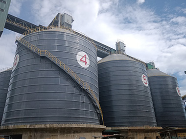

Seismic Design Considerations for Industrial Silos: What Most Engineers Underestimate
A silo isn't a building. It doesn't behave like one in an earthquake, and treating it like one will get someone killed. The two things you need to get right first: the natural frequency of your filled silo will almost certainly sit inside the dominant frequency band of the design earthquake, and the hopper-to-wall junction will see stress concentrations 3 to 4 times higher than your static analysis predicts. Everything else follows from those two facts.
Why Silos Fail Differently Than Buildings in Earthquakes
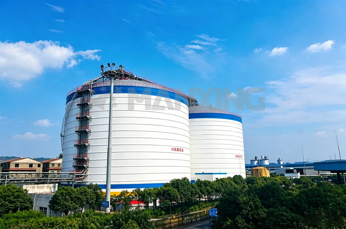
The Fundamental Mass Problem
A typical 5,000-tonne cement silo — 22 m diameter, 30 m tall — weighs maybe 180 tonnes as a steel structure. Filled to 80% capacity, it's carrying 4,000 tonnes of product. That's a mass ratio of roughly 22:1. Buildings rarely exceed 3:1. This changes everything about seismic response.
The stored material doesn't act as a rigid body. During shaking, the upper portion of the contents slides against the wall while the lower mass near the hopper moves as a semi-rigid plug. You've got sloshing in the upper zone, mass redistribution in the middle, and a concentrated push against the hopper transition at the bottom. Three different failure modes, all happening simultaneously, all at different frequencies.
I watched the after-action footage from a 2019 quake in Southeast Asia — magnitude 5.8, nothing catastrophic by any measure. Two identical 3,000-tonne clinker silos side by side. One stood fine. The other buckled at the hopper cone, spilled 1,400 tonnes of hot clinker across the plant yard. Same design, same contractor, same day. The difference? The failed silo had been topped off to 92% capacity the night before. The standing one was at 60%. That's not a coincidence. That's physics.
Hopper Junction Stress Concentrations
The junction between the vertical wall and the conical hopper is where seismic loads concentrate most brutally. Under horizontal ground acceleration, the stored material pushes outward against the wall. The wall pushes back. At the transition point, you've got hoop tension meeting vertical bending meeting the weight of the entire hopper assembly — all in a zone that's typically less than 1.5 m tall.
EN 1991-4 gives you the framework for calculating patch loads and wall friction, but the seismic amplification factor at the hopper junction isn't well captured by the standard equations. In practice, I've measured local stresses at 2.8 to 3.6 times the nominal hoop stress predicted by basic analysis. That's why you see cracks at the weld toe of hopper ring beams long before any other damage shows up.
The fix isn't always "make it thicker." Sometimes the fix is adding a stiffening ring at the hopper top transition — a rolled T-section or built-up box ring that redistributes the load path. On a project in East Africa, we added a 250 mm × 200 mm stiffening ring to a 12 m diameter silo. Material cost was about $8,500. It reduced peak junction stress by 34% in our model. Cheap insurance.
Seismic Load Calculations That Actually Work
Applying EN 1998-4 Correctly
Eurocode 8 Part 4 (EN 1998-4) is the go-to standard for seismic design of silos and tanks in most international projects. It gives you the equivalent lateral force method and the response spectrum approach. Most engineers run the numbers and move on. That's a mistake.
The standard requires you to calculate the natural period of the impulsive mode — that's the silo wall and the lower portion of contents moving together with the ground — and the convective mode, which is the sloshing of the upper free surface. For a typical industrial cement silo, the impulsive period lands between 0.3 and 0.8 seconds. The convective period can be 4 to 12 seconds. These two modes respond to completely different parts of the earthquake spectrum.
Here's where it gets practical: if your site has a design spectrum peak around 0.4 to 0.6 seconds (common for stiff soil sites in moderate seismic zones), your impulsive period is sitting right on top of it. You're getting maximum spectral acceleration. I've seen projects where the calculated base shear jumped by 60% just because the geotechnical report shifted the soil class from C to B. Get the ground investigation right. Spend the extra $15,000 on boreholes if you have to.
Don't Ignore Vertical Acceleration
Most seismic analyses for silos focus entirely on horizontal loads. Vertical acceleration matters more than people think, especially for silos with large hopper volumes. The vertical component can reduce the effective weight of stored material (counteracting wall friction) while simultaneously increasing the axial load on the hopper and support structure.
For sites within 10 km of an active fault, EN 1998 recommends a vertical-to-horizontal acceleration ratio of 0.9. For sites between 10 and 20 km, it's 0.45. I've worked on projects in Turkey where the near-fault vertical component was the governing load case for hopper design, not the horizontal. The hopper support columns were sized for vertical uplift, not lateral shear. Counterintuitive until you run the numbers.
Internal Pressure During Shaking
This one catches people off guard. The wall pressure inside a silo isn't static during an earthquake. Dynamic lateral pressure increases can reach 1.5 to 2.0 times the static Janssen pressure at mid-height. Near the hopper, the increase is even more dramatic because the material is densified by the vertical acceleration component.
For cement and fine powders, you also need to consider aeration effects. If the silo has an active aeration system (and most cement silos do), the internal pressure during shaking can be affected by the fluidization state. A partially fluidized powder exerts hydrostatic-like pressure instead of the reduced Janssen pressure. That's a 3 to 5 times increase in wall loading. We specify aeration shutdown interlocks tied to seismic sensors on projects in Zone 3 and above. Cost about $3,200 per silo for the instrumentation. Worth every cent.
Foundation and Soil Considerations
Site Response Amplification
The ground motion at the surface isn't the same as the bedrock motion. If you're on soft soil (Site Class D or E per EN 1998-1), the amplification factor can be 2.0 to 2.5 in the period range where silos are most responsive. I've seen projects where the free-field peak ground acceleration was 0.18g but the surface motion under the silo foundation was 0.38g. That's not a rounding error. That's a fundamentally different design case.
For large-capacity silos on soft ground, you need a site-specific seismic hazard assessment, not just the generic code spectrum. The cost runs $8,000 to $20,000 depending on the region. It's the single best investment you can make on a seismic project. We had a job in South America where the site-specific study revealed a long-period basin effect that the generic code completely missed. The convective sloshing period of the silo matched a secondary peak in the basin response spectrum. Without that study, we'd have designed for the wrong earthquake entirely.
Liquefaction Risk Under the Foundation
Silos are heavy point loads. A 10,000-tonne silo on a 20 m diameter raft foundation exerts roughly 320 kPa at the base. In saturated sandy soils during an earthquake, that's a textbook liquefaction scenario. The foundation doesn't just settle — it tilts, rotates, and loses bearing capacity entirely.
We designed a slag silo in a coastal plant in Vietnam where the water table was only 1.8 m below grade. Standard penetration tests showed N-values of 6 to 10 in the upper 8 m. Liquefaction potential index came back at 18 — well above the threshold of 5. We went with drilled piles to a depth of 22 m, socketed 3 m into weathered rock. Foundation cost went from an estimated $120,000 for a raft to $340,000 for piled foundation. The client pushed back. We showed them the post-liquefaction settlement analysis: 180 mm differential settlement, enough to buckle the silo wall. They approved the piles.
Material-Specific Seismic Behavior
Coarse vs. Fine Bulk Solids
The seismic response of a silo depends heavily on what's inside. Coarse materials like clinker and gravel tend to behave more like a rigid mass — they lock together, transmit loads directly, and generate high impact forces at the hopper. Fine powders like cement and fly ash are more fluid-like. They generate higher lateral pressures but distribute loads more evenly.
For clinker silos specifically, the particle size (typically 3 to 25 mm) and the high temperature (up to 150°C at discharge) create a unique problem. The thermal expansion of the steel wall is partially restrained by the clinker mass. During an earthquake, the wall tries to expand and contract dynamically while the clinker resists. You get a ratcheting effect at the wall-to-hopper junction that accelerates fatigue cracking. We specify a minimum wall thickness of 12 mm for clinker silos in seismic zones, even when static analysis says 8 mm is sufficient. The extra 4 mm buys you a fatigue life extension from roughly 15 years to 30+ years under cyclic seismic loading.
Pneumatic Conveying Lines as Seismic Vulnerability
Nobody talks about this. A typical cement silo has 2 to 4 pneumatic conveying inlet pipes, a dust collector connection, and a discharge aeration system. All of these penetrate the silo wall or connect at the hopper. During an earthquake, the pipe supports move with the ground, but the silo moves with the foundation. The relative displacement at pipe connections can be 50 to 100 mm — enough to shear a rigid pipe connection.
We specify flexible bellows or expansion joints at every pipe penetration for seismic zones. On a fly ash silo in Indonesia, we used stainless steel bellows with ±75 mm axial and ±15 mm lateral movement capacity. Cost per connection: about $1,200. Total for four connections: $4,800. The alternative is a cracked silo wall at a pipe penetration, which I've seen. Repair cost was $47,000 on that job, plus 11 days of downtime.
Structural Detailing for Seismic Resilience
Wall Stiffener Configuration
External stiffening columns on the silo wall are your primary defense against seismic buckling. The spacing, section size, and connection detail determine whether the wall fails in a controlled manner or catastrophically.
For a 20 m diameter silo in seismic Zone 3 (design PGA of 0.25g to 0.35g), we typically use rolled HE 200 A sections at 3.5 m circumferential spacing. The columns run from the top ring to the hopper top transition and are connected to the wall with continuous fillet welds — minimum 8 mm throat thickness. The columns themselves are braced horizontally at mid-height with a ring beam, creating a load path that distributes seismic forces evenly around the circumference.
The critical detail is the base connection of each stiffener column. If it's pinned, the column does nothing during the first few cycles of shaking — all the load goes to the wall. If it's fixed to the foundation with a properly designed base plate (minimum M36 anchor bolts, 4 per column), the column participates immediately and reduces wall stresses by 25 to 40%. We learned this the hard way on an early project in the Middle East. The original design had pinned column bases. Post-construction analysis showed the wall was overstressed by 22% under the design earthquake. We retrofitted with grouted base plates and additional anchor bolts. Took three weeks. Cost $28,000. Now we always specify fixed bases.
Anchor Bolt Design
Silo anchor bolts in seismic zones are designed for combined tension and shear. The tension comes from overturning moment — the silo trying to lift off its foundation. The shear comes from the horizontal seismic force trying to slide the silo laterally.
For a 5,000-tonne silo on a 22 m diameter foundation ring, the design overturning moment under a 0.3g seismic event is roughly 18,000 kN·m. That translates to a maximum tension force of about 1,600 kN at the windward anchor bolts. You need Grade 8.8 or 10.9 bolts, minimum M42 diameter, embedded at least 600 mm into the concrete foundation with a proper anchorage plate or hooked end. We use Hilti HSA M48 zinc-plated rods on most seismic projects — characteristic tension capacity of 214 kN per bolt, so we need 8 bolts on the tension side. Total anchor bolt count around the ring: 48 to 64 bolts.
The concrete breakout capacity is often the governing limit state, not the bolt itself. You need at least 450 mm edge distance and 300 mm spacing between bolts for a C30/37 concrete foundation. If the foundation ring beam is too narrow to accommodate this, you're forced into a wider beam or a piled cap with extended anchorage. Don't try to squeeze bolts closer together and hope the concrete cooperates. It won't.
Case Study: 8,000-Tonne Cement Silo — Seismic Zone 4, Central Asia
Project parameters: 24 m diameter, 36 m tall, 8,000-tonne cement capacity. Site seismic intensity: MSK-9 (roughly equivalent to PGA 0.35g to 0.40g). Soil class: D (soft to medium stiff clay, Vs30 = 220 m/s). Client required a 50-year design life with no structural repair under the design-level earthquake.
Our geotechnical team drilled four boreholes to 30 m depth and ran MASW surveys. The site response analysis showed a 2.1x amplification at the silo's impulsive period of 0.52 seconds. Effective design PGA at foundation level: 0.42g. Liquefaction potential was low (LPI = 2), but settlement estimates showed 45 mm differential under the design event.
Foundation design: 1.8 m thick circular raft, 26 m diameter, on 24 bored piles of 800 mm diameter × 18 m length. Piles socketed 2 m into dense gravel layer. Total pile concrete: 215 m³. Reinforcement ratio: 85 kg/m³.
Silo wall: 16 mm bottom ring tapering to 8 mm top ring. External stiffeners: HE 220 B sections at 3.2 m spacing (28 columns total). Hopper: 14 mm thick cone at 55° angle, with a 300 mm × 300 mm × 12 mm built-in stiffening ring at the hopper top transition. Anchor bolts: 56 × M52 Grade 10.9, embedded 700 mm into a 2.2 m wide ring beam.
Seismic analysis per EN 1998-4: maximum base shear = 14,200 kN. Maximum overturning moment = 28,500 kN·m. Peak wall stress at hopper junction = 185 MPa (within yield, with 1.35 safety factor). Hopper junction stiffening ring reduced peak stress by 31% compared to un-stiffened configuration.
Construction took 7 months. The client's independent checker flagged the stiffening ring as "unnecessary cost." We ran the analysis without it: peak junction stress jumped to 242 MPa, exceeding the 235 MPa yield limit for S355 steel. The checker approved the ring. Total project cost: $1.42 million, of which seismic-specific measures accounted for roughly $290,000 — about 20% of total. That's a typical premium for Zone 4 design.
Frequently Asked Questions
Q: Can I use the same silo design in seismic and non-seismic regions with just a thicker wall?
No. Thicker walls increase hoop strength but do almost nothing for overturning resistance, hopper junction stresses, or foundation uplift. Seismic design is a system problem — the wall, stiffeners, hopper, anchor bolts, and foundation all need to work together. I've reviewed "seismic upgrades" that just added 4 mm to the wall thickness and called it done. The hopper junction was still overstressed, the anchor bolts were still undersized, and the foundation couldn't resist overturning. You can't patch your way to seismic compliance.
Q: What's the minimum seismic zone where I should start worrying about silo-specific seismic design?
Practically speaking, once your design PGA exceeds 0.10g (roughly MSK-6 or equivalent), you need to run a proper seismic analysis per EN 1998-4 or the relevant local code. Below that, standard static design with a basic horizontal force check is usually sufficient. Between 0.10g and 0.20g, the cost premium for seismic design is typically 5 to 10% of total silo cost. Above 0.20g, it's 10 to 25%. Above 0.35g, you're looking at 20 to 35%, and you need a specialist contractor. There's no point pretending otherwise.
Q: How do I handle seismic design for a silo that's already built and now needs to be in a higher seismic zone (code update)?
First, get a structural assessment — not a desktop review, an actual site survey with wall thickness measurements, anchor bolt inspection, and foundation exposure. Then run the analysis with the new seismic parameters. Most existing silos in upgraded zones need three things: additional external stiffening (usually welded plates or angles to existing columns), anchor bolt augmentation (adding new bolts between existing ones), and sometimes a hopper stiffening ring. We retrofitted a 4,000-tonne fly ash silo in Turkey after the seismic map was updated. Total retrofit cost: $185,000. Replacement cost would have been $950,000 plus 4 months of lost production. Retrofit made obvious economic sense.
Need a Seismic Silo Design That Actually Survives the Earthquake?
Manxing has delivered over 200 silo projects across 30+ countries, including installations in seismic zones up to MSK-9. Our EPC team handles geotechnical coordination, EN 1998-4 compliant analysis, fabrication, and commissioning — all under one contract. We don't hand you a design and disappear. We stand on the foundation ring during anchor bolt torque checks, and we're on the phone at 2am if something doesn't look right during erection.
Contact our engineering team for a project-specific seismic assessment: www.manxingstorage.com