
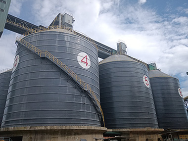

Steel Silo Plasma Cutting Quality: What Actually Matters on Site
Plasma cutting quality for steel silos determines whether your shell plates fit together with 2 mm gaps or 8 mm gaps — and that difference costs you weeks of rework. The short answer: cut quality is defined by edge squareness, dross adherence, and heat-affected zone depth, all of which you can control with the right parameters and consumable management. Here's what 15 years of watching plates get cut, shipped, and bolted together has taught me.
1. Why Plasma Cutting Quality Dictates Silo Assembly Speed
I've stood on a commissioning site in Vietnam where the shell plates wouldn't sit flat against each other. The edges were wavy — not dramatically, maybe 3 to 4 mm out of true over a 2-meter span. But that meant every single weld joint needed shimming, grinding, or both. The erection crew lost 11 days on a 3,000-tonne cement silo. Eleven days. The cutting had been done cheaply, fast, and without anyone checking edge quality against a straightedge.
1.1 The Fit-Up Problem Nobody Budgets For
When you're fabricating shell plates for a bolted steel silo, each plate needs to mate with its neighbor within a tolerance of ±1.5 mm along the seam. That's not a suggestion — it's what keeps the shell round and the bolt pattern aligned. Plasma cutting that produces beveled edges or inconsistent kerf width pushes you outside that window fast.
A typical 1,000-tonne capacity cement silo uses somewhere between 40 and 60 shell plates per ring. If even 20% of those plates need edge grinding before they'll fit, you're looking at an extra 2 to 3 minutes per plate. Multiply that across 15 rings and you've added a full day of labor. On a 5,000-tonne clinker silo with 20+ rings, it's worse.
1.2 Weld Quality Starts at the Cut Edge
Here's something that doesn't get talked about enough: the cut edge is your weld prep. If the plasma cut leaves a 0.5 mm oxide layer or a 1 mm deep gouge along the edge, your welder is either burning through inconsistency or filling it with extra passes. Neither is good.
For fillet welds on silo shell seams — typically 6 mm to 8 mm leg length — the cut edge needs to be clean enough that the weld pool flows consistently. I've seen welders add 30% more filler metal just to compensate for poor cut edges. On a silo with 200 meters of shell seam welding, that's real money.
2. The Parameters That Actually Control Cut Quality
Plasma cutting isn't magic. It's physics. And the physics are well understood — which means bad cuts are almost always a parameter problem, not a machine problem.
2.1 Amperage, Speed, and Gas Selection
The relationship is straightforward: higher amperage cuts thicker plate but generates more heat. Faster travel speed reduces the heat-affected zone but risks incomplete penetration. You're balancing on a knife edge, and the sweet spot moves with every material thickness.
For the 6 mm to 12 mm carbon steel plate that makes up most silo shells, here's what works in practice:
- 6 mm plate: 60 to 80 A, travel speed 2,500 to 3,500 mm/min, compressed air or nitrogen plasma gas
- 10 mm plate: 100 to 130 A, travel speed 1,500 to 2,200 mm/min, nitrogen or argon-hydrogen mix
- 12 mm plate: 130 to 200 A, travel speed 800 to 1,500 mm/min, argon-hydrogen for best edge quality
Compressed air is the cheapest option and works fine for 6 mm plate where edge quality isn't critical. But once you're cutting 10 mm or thicker for silo shell plates that need to mate precisely, switch to nitrogen or an argon-hydrogen mix. The edge squareness improves dramatically — you'll see the difference with a straightedge immediately.
2.2 Consumable Wear: The Silent Quality Killer
Electrodes and nozzles wear. That's not news. What surprises people is how fast cut quality degrades once consumables are past their useful life.
A typical electrode lasts 1 to 2 hours of actual arc-on time. A nozzle lasts maybe 2 to 3 hours. After that, the arc starts to wander. The kerf widens. Dross appears on the bottom edge. And because the degradation is gradual, operators don't notice until they've cut 20 plates with a dying nozzle.
At Manxing, we track consumable hours on every job. When a nozzle hits 2 hours, it's replaced — not inspected, not evaluated, replaced. The cost of a nozzle is $8 to $15. The cost of reworking a mis-cut shell plate is $200 to $500 in labor and material. The math isn't close.
2.3 Standoff Distance and Torch Height Control
The torch needs to maintain a consistent standoff — typically 3 to 6 mm from the plate surface — throughout the cut. On a flat table with a new plate, that's easy. On a plate that's slightly warped from rolling stresses or has mill scale that's thicker in some areas, it's not.
Automatic torch height control (THC) systems use arc voltage feedback to maintain standoff. They work well, but they need to be calibrated. I've seen THC systems that were set 1.5 mm too high, which meant the arc was stretched and the cut edge had a 2° bevel across the entire plate. On a 1,200 mm wide plate, that's a 4 mm mismatch at the edge. Enough to cause fit-up problems.
Check your THC calibration at the start of every shift. Takes 5 minutes. Saves hours.
3. Measuring Cut Quality: What to Check and How
You can't manage what you don't measure. And "looks fine to me" isn't a measurement.
3.1 Edge Squareness and Bevel Angle
The cut edge should be perpendicular to the plate surface. For silo shell plates, the maximum acceptable bevel is 3° — and that's the absolute limit. Ideally you want under 1.5°.
Measure it with a bevel protractor or a digital angle gauge. Check at three points along each cut edge: start, middle, end. If any point exceeds 2°, the plate needs re-cut or edge grinding.
Here's the practical impact: a 3° bevel on a 10 mm plate creates a 0.52 mm offset at the edge. Stack that across a butt joint and you've got a 1.04 mm mismatch. Still within tolerance for most silo welds, but you're eating into your margin. On a 12 mm plate, the same 3° bevel gives you 0.63 mm per side. Now you're at 1.26 mm mismatch, and your welder is going to complain.
3.2 Dross and Adhesion
Dross is the resolidified metal that sticks to the bottom edge of the cut. Some dross is normal. Heavy dross that requires a grinder to remove is not.
For silo fabrication, the rule is simple: dross must be removable with a light scrape or wire brush. If you need an angle grinder with a flap disc, the cut parameters were wrong.
Fast travel speed produces dross that's hard and tightly adhered — the metal didn't have time to fully eject from the kerf. Slow travel speed produces a softer, more porous dross that's easier to remove but indicates you're putting too much heat into the plate. Either way, something's off.
3.3 Heat-Affected Zone Depth
The heat-affected zone (HAZ) is the area of base material that didn't melt but was altered by the heat of the plasma arc. For carbon steel silo plate, the HAZ from plasma cutting typically extends 0.5 to 1.5 mm from the cut edge.
Why does this matter? Because the HAZ is harder and more brittle than the base metal. In a silo shell that's subject to cyclic loading from filling and emptying — we're talking 500 to 2,000 cycles per year depending on the operation — the HAZ is where fatigue cracks can initiate.
For most industrial silos storing cement, clinker, or fly ash, the HAZ depth from plasma cutting isn't a structural concern. The stresses are low and the cycle counts are manageable. But if you're designing a silo for a high-cycle application — say, a day bin that fills and empties 10 times a day — you should specify that cut edges be ground to remove the outer 0.5 mm. It's cheap insurance.
4. Material-Specific Considerations for Silo Steels
Not all steel cuts the same. The material you're cutting for your silo affects every parameter.
4.1 Carbon Steel (Q235B, Q345B, S235JR, S355JR)
This is the bread and butter of silo construction. Q235B and its equivalents cut cleanly with plasma. The main issue is mill scale — that blue-black oxide layer on hot-rolled plate. Mill scale is harder than the base metal and can cause inconsistent cut quality if it's thick or patchy.
For shell plates, we specify that mill scale be removed from the cut line — either by grinding a 20 mm wide strip along the cut path or by using plate that's been pickled and oiled. It adds a step, but it eliminates a variable.
Q345B (16Mn) has higher manganese and silicon content, which means it cuts slightly slower than Q235B at the same thickness. Drop your travel speed by 10% to 15% and you'll get equivalent edge quality.
4.2 Stainless Steel (304, 316)
Stainless steel silos are less common but show up in food-grade applications, chemical storage, and some specialty mineral products. Stainless cuts beautifully with plasma — the edge is cleaner and more consistent than carbon steel.
The catch: you can't use compressed air as the plasma gas on stainless. The air reacts with the chromium in the steel, creating a rough, oxidized cut edge. Use nitrogen or an argon-hydrogen mix. The edge quality improvement is immediately visible.
Also, stainless work-hardens. If your travel speed is too slow, the HAZ can develop micro-cracks. Keep the speed up and the amperage appropriate for the thickness.
4.3 Abrasion-Resistant Steels for Wear Zones
Some silos — particularly those handling abrasive materials like clinker, slag, or coal — use abrasion-resistant (AR) steel in the lower shell sections and cone. AR plate with a Brinell hardness of 400 or 500 cuts with plasma, but the edge quality is harder to control.
The high alloy content in AR steel means the cut edge can have a harder, more brittle HAZ. For these applications, we typically specify post-cut grinding of the edge to a depth of 1 mm. It adds cost, but it prevents edge cracking during assembly and welding.
5. Common Defects and How to Fix Them
I've seen every plasma cutting defect there is. Here are the ones that actually matter for silo fabrication.
5.1 Top Edge Rounding
The top corner of the cut edge is rounded instead of sharp. This happens when the arc is too hot for the travel speed — the plasma stream melts back into the top surface before the cut front reaches it.
Top edge rounding of 0.5 mm or less is acceptable. Beyond that, you're losing material thickness at the weld prep, which reduces weld throat and joint strength. Fix it by increasing travel speed or reducing amperage.
5.2 Gouging and Striations
Deep striations (drag lines) on the cut face indicate the arc is struggling — usually a worn consumable or incorrect gas flow. Gouging — where the cut face has a groove or irregularity — is often caused by inconsistent standoff height.
Both defects are unacceptable on silo shell plate edges that will be welded. The cut face should be smooth enough that you can run your fingernail along it without catching. If it catches, it needs to be ground smooth.
5.3 Incomplete Cut-Through
The plasma arc doesn't fully penetrate the plate, leaving uncut material at the bottom edge. This is almost always a speed-too-high or amperage-too-low problem. On a silo shell plate, an incomplete cut means the plate won't separate cleanly, and the torn edge that results is a stress concentrator.
If you find incomplete cut-through on a plate, don't try to finish it with a grinder. Re-cut the edge with corrected parameters. The torn metal has a different microstructure than a clean plasma cut, and it's more prone to cracking.
6. Quality Control Workflow for Silo Shell Plate Cutting
Here's the QC workflow we use at Manxing for every silo fabrication project. It's not complicated, but it's consistent.
6.1 First-Article Inspection
Before cutting any production plates, cut one test plate from the same batch of material. Measure edge squareness, check for dross, examine the cut face for striations. If the test plate passes, cut the production batch. If it doesn't, adjust parameters and cut another test plate.
This takes 30 minutes and costs one plate of material. It's the cheapest insurance you'll ever buy.
6.2 In-Process Checks
Every 10th plate gets a full inspection: edge squareness at three points, dross check, visual examination of the cut face. Every plate gets a visual check by the operator. If anything looks off, that plate gets flagged for full inspection.
We also check consumable condition every 2 hours of arc-on time. Electrode and nozzle are replaced on a fixed schedule, not based on visual inspection. By the time a worn nozzle looks bad to the eye, it's been cutting poorly for the last 30 minutes.
6.3 Final Inspection Before Shipment
Before plates leave the fabrication shop, we check every cut edge with a straightedge and feeler gauge. Maximum allowable gap between the straightedge and the plate edge is 1.0 mm over a 1-meter span. Plates that don't meet this get re-cut or edge-ground.
We also verify plate dimensions. A typical silo shell plate is 1,200 mm wide (one ring segment) and 2,000 to 3,000 mm long. The length tolerance is ±2 mm. If the plasma cut has drifted, the plate might be 3 mm too long or too short, which causes problems during assembly when the bolt holes don't align.
Case Study: 5,000-Tonne Clinker Silo — Cut Quality Impact on Erection Schedule
A cement plant in the Philippines needed a 5,000-tonne clinker silo. The shell was 22 meters in diameter, 36 meters tall, built from 10 mm and 12 mm Q345B plate. Total shell plate count: 288 plates across 18 rings.
The original fabricator cut all 288 plates with compressed air plasma at a single set of parameters — 130 A for both 10 mm and 12 mm plate. The 10 mm plates came out fine. The 12 mm plates had heavy dross on the bottom edge and a 2.5° bevel on the cut face.
When the plates arrived at site, the erection crew spent an average of 4 minutes per 12 mm plate cleaning dross and grinding bevels. That's 144 plates × 4 minutes = 9.6 hours of extra work. Not catastrophic, but unnecessary.
More seriously, the bevel on the 12 mm plates meant the butt joints had a V-shaped gap instead of a square gap. The welders had to add an extra fill pass on every 12 mm seam. With 72 meters of 12 mm vertical seam welding, that added approximately 18 kg of filler metal and 12 hours of welding time.
Total cost impact: roughly $4,200 in additional labor and material. On a project with a fabrication budget of $180,000, that's 2.3%. Not huge in percentage terms, but it's pure waste — money spent fixing a problem that shouldn't have existed.
When we took over the QC review for the next silo on the same project, we specified separate cutting parameters for 10 mm and 12 mm plate, switched to nitrogen plasma gas for the 12 mm, and implemented the consumable replacement schedule. The second silo's plates arrived at site ready to bolt together. Zero rework.
Frequently Asked Questions
Q: Can plasma-cut edges be welded directly, or do they need grinding first?
For carbon steel silo plate up to 12 mm thick, plasma-cut edges can be welded directly if the cut quality is good — meaning minimal dross, edge squareness within 3°, and no visible gouging. If the cut has heavy dross or visible striations deeper than 0.5 mm, grind the edge before welding. For high-cycle silos or applications where fatigue is a concern, grind the outer 0.5 mm off the cut edge regardless of visual quality.
Q: What's the maximum plate thickness for plasma cutting on silo shells?
Practical limit for quality plasma cutting on silo shell plate is about 25 mm. Beyond that, you're better off with oxy-fuel cutting for the heavy shell sections or cone components. Most industrial silos use plate in the 6 mm to 16 mm range, which is well within plasma's sweet spot. For the 20 mm to 25 mm transition zone, plasma works but you need high-amperage systems (200 A+) and argon-hydrogen gas to maintain edge quality.
Q: How does plasma cutting compare to laser cutting for silo plate?
Laser cutting gives better edge quality — tighter tolerances, smaller HAZ, cleaner edges. But for silo shell plates that are 2,000 mm to 3,000 mm long and 10 mm to 12 mm thick, laser is significantly more expensive and slower. The edge quality advantage of laser doesn't translate into meaningful assembly or structural benefits for most silo applications. Plasma, done right, is the right tool for the job. Laser makes sense for thin-gauge components — hopper liners, dust collector housings, structural brackets — but not for main shell plate.
Need Help with Silo Fabrication Quality?
Manxing provides EPC silo contracting with full in-house fabrication QC. We've delivered over 200 silos across 30+ countries for cement, clinker, fly ash, coal, and slag storage. Every shell plate is inspected before it leaves our shop.
Contact our engineering team for a fabrication quality review or project consultation:
www.manxingstorage.com